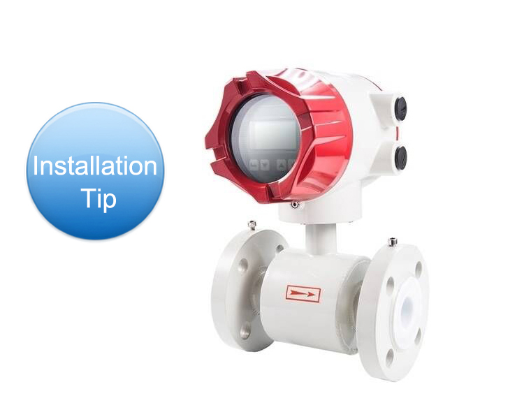
Installation Tips of Magnetic Flow Meter
Magnetic flow meter is a kind of instrument to measure the flow of conducting fluid according to the electromotive force induced by the external magnetic field by applying the principle of electromagnetic induction. The structure of electro magnetic flow meter is mainly composed of magnetic circuit system, measuring conduit, electrode, shell, lining and converter.
In addition to understanding what the electromagnetic flowmeter is, we also need to pay attention to some places in the daily installation. In this article, atoflowmeter.com will give you some tips about installation.
Installation Requirements For Straight Pipe Sections
- Firstly, take note that the flow meter itself cannot be utilized as a load support point. Instead, a clamp must be applied to the load-bearing pipe next to it. The electro magnetic flow meter upstream also needs a specific length of the straight pipe section to acquire a normal measurement degree, but its length is shorter than that of the majority of other flow meters.
- To prevent the butterfly valve flange from entering the meter measuring tube, use a 900 elbow, T-shaped pipe, concentric reducer, fully open gate valve after the meter that is 5 times the diameter of the flange connection surface from the inlet end (5D) length of the straight pipe section, and a downstream straight pipe section for (2–3) D. The upstream and downstream straight pipe length standards or calibration techniques are also inconsistent, with some magnetic flowmeter requirements that are higher than the typical high requirements. This is to guarantee that the current 0.5 level of instrument accuracy criteria are met.
Installation of the Negative Pressure Pipe System
- Negative pressure pipe systems must carefully apply a fluorine plastic lining meter. Positive pressure pipe systems should be prevented from producing a negative pressure, such as when a liquid system's temperature is higher than room temperature. In this case, shut off the meter's upstream and downstream shut-off valves to stop operation.
- The meter should be installed close to the negative pressure prevention valve.
Installation Position and Flow Direction
- There are no constraints on the meter installation directions, which can be horizontal, vertical, or inclined. Nonetheless, to guarantee that the processing pipeline and the measurement tube are coaxial. Axis deviation shouldn't be more than 2 mm. Bottom-up flow, good vertical installation, measuring solid-liquid two-phase fluid.
- This can prevent solid phase precipitation at low flow rates as well as the drawbacks of horizontal installation when the lower portion of the lining is locally significantly deteriorated.
- In order to protect the lining of the magnetic flow meter next to a pipeline from heat and to ensure that the instrumentation converter signal line is not connected, it must be installed horizontally with the electrode axis parallel to the horizon rather than perpendicular to it because the top electrode is more likely to have liquid on it and the electrode in the ground to be covered by sediment.